Ruthenium-based dyes for Dye-sensitized Solar Cells
Dr. Hans Desilvestro, Dr. Yanek Hebting
Dyesol Ltd., 3 Dominion Place, Queanbeyan NSW 2620 AUSTRALIA
Working principle of dye-sensitized solar cells
Dye-sensitized Solar Cells (DSCs) are 3rd generation solar cells combining the promise of high efficiency with low production costs. While present-day DSCs provide light-to-electricity conversion of up to 11%,1-3 significant further improvement is envisaged through optimized materials and novel cell and module architectures. In addition, DSC devices can be manufactured to be semi-transparent to harvest light from practically any angle and direction paving their way for use as photovoltaic windows in buildings or small devices.

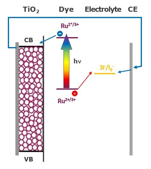
Figure 1. Schematic of electron pathway in a DSC system
The schematic shown in Figure 1 depicts the working principle of a DSC:
- Light is absorbed by a monomolecular layer of dye chemisorbed to a thin film of nanocrystalline TiO2 promoting an electron from the Ru2+ based ground state to an excited state (Ru2*).
- The excited electron is then transferred within a very short time (pico to femtoseconds) into the conduction band (CB) of TiO2. This leads to an effective charge separation, with a negative charge within the titania phase and a positive charge on surface-adsorbed Ru3+.
- The Ru3+ species is then reduced very rapidly (within nanoseconds) by an iodide anion (I¯ ) present in the electrolyte system. The electron injected into TiO2 in the previous step diffuses through the nano-network of particles until it reaches the electrically conductive surface for current collection, e.g. a thin layer of conductive transparent oxide on glass, plastic or a metallic substrate.
- The electric charge thus extracted from the photoanode as a current can be utilised to provide useful electric power.
- In order to close the electric circuit, the negative charges are directed to the surface of a counter electrode (CE) where I3¯ is reduced to I¯. Thus no net chemical reaction occurs within a DSC.
DSC operation is much closer to photosynthetic processes than operation of standard solid-state photovoltaic devices such as silicon-based solar cells. As with photosynthesis, the effectiveness of the light conversion in DSCs depends on the relative speed of reactions, i.e. kinetics. The electron injection into the titania conduction band is much faster than electronic relaxation processes back to the ground state or chemical side reactions involving the excited state of the dye. Moreover, the reduction of the oxidized dye (Ru3+) by I¯ is significantly faster4 than the direct recombination reaction between the injected electron and Ru3+.
Ruthenium Dyes
In dye-sensitized solar cells, the dye is one of the key components for high power conversion efficiencies. In recent years, considerable developments have been made in the engineering of novel dye structures in order to enhance the performance of the system. In particular, amphiphilic homologues of the pioneering ruthenium based N-3 dye have been developed. These amphiphilic dyes display several advantages compared to the N-3 dye such as:
- a higher ground state pKa of the binding moiety thus increasing electrostatic binding onto the TiO2 surface at lower pH values,
- the decreased charge on the dye attenuating the electrostatic repulsion in between adsorbed dye units and thereby increasing the dye loading,
- increasing the stability of solar cells towards water-induced dye desorption,
- the oxidation potential of these complexes is cathodically shifted compared to that of the N-3 sensitizer, which increases the reversibility of the ruthenium III/II couple, leading to enhanced stability.5

N-3C26H16N6O8RuS2 Mol Wt: 705.64

N-719C58H86N8O8RuS2 Mol Wt: 1188.55

Z-907C42H52N6O4RuS2 Mol Wt: 870.10
Figure 2. Ruthenium-based N-3, N-719 and Z-907 dyes.
| Synonym | Product | Description | Product No. |
|---|---|---|---|
| N-3 | cis-Bis(isothiocyanato) bis(2,2’-bipyridyl-4,4’-dicarboxylato ruthenium(II) |
| 703206 |
| N-719 | Di-tetrabutylammonium cis-bis(isothiocyanato)bis(2,2’-bipyridyl-4,4’-dicarboxylato)ruthenium(II) |
| 703214 |
| Z-907 | cis-Bis(isothiocyanato)(2,2’-bipyridyl-4,4’-dicarboxylato)(4,4’-di-nonyl-2’-bipyridyl)ruthenium(II) |
| 703168 |
Ruthenium-based dyes exhibit ligand-centered charge transfer (LCCT) transitions (π - π*) as well as metal-to-ligand charge transfer (MLCT) transitions (4d - π*) that can be observed in the UV/Vis spectra of N-719 and Z-907 dyes (Figure 3). The absorption bands at lower energies represent the MLCT transitions (λ1 and λ2) whereas the more energetically demanding transitions (λ3 and λ4) correspond to LCCT transitions.6

Figure 3.UV/Vis spectra of N-719 (Product No. 703214) and Z-907 (Product No. 703168) dyes.
DSC Cell
A translucent DSC with an active area of 0.88 cm2 (8 mm x 11 mm) based on Dyesol test cell hardware7,8 prepared with N-719 dye is illustrated in Figure 4. The orange area is a result of the dye-modified titania; the yellow color is given by the electrolyte of the system.

Figure 4.Dyesol translucent test cell manufactured with N-719 dye (scale in nm)
JV Curves
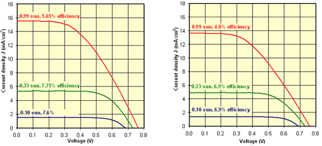
Standard test cells are characterised by typical JV plots as shown in Figure 5 when tested at three different sun levels (1 sun corresponds to 100 mW cm-2). The voltage,V, and the current density, J (mA cm-2), at the maximum power point are represented by Vmax and Jmax. Therefore the efficiencies can be calculated by:
η (%) = (Vmax x Jmax) / (sun level)

Figure 5.JV curves for N-719(left) and Z-907(right) dye-based DSC devices.
With commercially relevant low volatility electrolyte systems, typical short circuit currents are 15.5 mA cm-2 and 13.7 mA cm-2 at full sun for an efficiency of 5.7% and 4.8% for N-719 and Z-907 respectively. The efficiencies characteristically increase at lower sun levels in DSC systems, when compared to full sun level efficiencies, to 7.8% (5.2 mA cm-2) and 7.6% (1.5 mA cm-2) for N-719 and to 6.9% (4.8 mA cm-2) and 6.9% (1.4 mA cm-2) for Z-907 at 1/3 sun and 1/10 sun respectively.
References
Zaloguj się lub utwórz konto, aby kontynuować.
Nie masz konta użytkownika?