Microfluidic-Assisted Manufacturing of Materials for Nanomedicine
Mike Geven1, Nora Francini1, Roberto Donno1, Nicola Tirelli1,2
1Laboratory of Polymers and Biomaterials, Fondazione Istituto Italiano di Tecnologia, 16163, Genova, Italy., 2Division of Pharmacy and Optometry, School of Health Sciences, Faculty of Biology, Medicine and Health, The University of Manchester
Material Matters, 2019, 14.3
- Introduction
- Nanoparticle Manufacturing
- Flow vs Batch Nanomanufacturing Processes
- The Problem of Mixing
- Solutions Developed to Accelerate Mixing
- Examples of Microfluidic-Assisted Nanomanufacturing
- Conclusions and Outlook
Introduction
This paper is about various preparative processes for nanomaterials designed to carry and deliver drugs, known as nanocarriers. Nanocarriers can affect both the pharmacokinetics (biodistribution, elimination, metabolism) and the pharmacodynamics (interactions with biological targets) of a drug, allowing to a) increase its dose well above its water solubility, b) change its concentration in body compartments, possibly and preferentially addressing it to target organs, c) reduce its elimination rate and protect it from degradation [pharmacokinetic factors], d) present it to cells and/or e) deliver it to cell compartments in a more efficacious fashion [pharmacodynamic factors]. Thanks to the potential access to a broader therapeutic spectrum, a number of nanomedicinebased formulations are now in clinical use (Table 1), having been approved by the United States Food and Drug Administration (FDA) and the European Medicines Agency (EMA). On the other hand, the development of nanomedicine has significant hurdles to overcome, most importantly in the precise description and repr to most nanomedicines not being ‘molecularly defined’: they comprise different chemical species, often with multiple phase boundaries, making classical molecular analysis not applicable. For example, the very concept of molarity (or molecular weight) is not applicable to nanoparticles.
As a practical example of the hurdles encountered in nanomedicine development, we can consider what it takes to evaluate a ‘nanosimilar’ (the generic equivalent of a nanomedicine);1 its therapeutic equivalence to a pre-existing nanomedicine can be expected only having established a) its pharmaceutical equivalence, i.e. the new product has similar physico-chemical descriptors, typically referred to as critical quality attributes (CQAs), and b) its bioequivalence, i.e. the active principle is made available at the same rate and same extent in the same sites. However, failure in (a) (=poorly reproducible CQAs) implies failure in (b) (=poorly reproducible pharmacokinetics), and therefore precisely described and reproducible CQAs are a necessary requisite for therapeutic efficacy. Of note, they are necessary but not sufficient; for example, poor bioequivalence may occur also when pharmaceutical equivalence appears to be achieved (see the generic PEGylated liposomal Lipodox compared to Doxil2).
For nanomedicines, the most important CQAs are size and size distribution, in addition to the often related parameters of surface charge and drug loading;3 this is not surprising since size (number), size distribution, and surface area are considered the critical descriptors of a nanomaterial, as per its EU commission definition.4 The first target of any pharmaceutical nanomanufacturing process is therefore to precisely and reproducibly control the size/size distribution of the nanomedicines.
Nanoparticle manufacturing
Herein we discuss nanomanufacturing in aqueous dispersion, specifically focusing on the bottom-up (through aggregation or agglomeration) production of nanoparticles; with this word we refer to nanomaterials with a predominantly elastic mechanical behaviour (solid-like, thereby including nanocrystals in this class), as opposed to nanodroplets, emulsions, self-assembled aggregates (micelles, vesicles) etc. that are mostly viscous in nature. From a processing point of view, this separation is important because the slow/arrested dynamics of elastic materials (high Deborah numbers) means that their morphology, size, and composition, i.e. their CQAs most often end up being determined by kinetic factors such as how the precursors are mixed (the fluidodynamics of the system), rather than thermodynamics. In view of the criticality of kinetic factors, flow-based and in particular, microfluidic-assisted processes have specific advantages, but also some important caveats.
Flow vs batch nanomanufacturing processes
Pioneered in the late 2000s,5 flow-based processes have become increasingly popular to produce formulations for drug delivery. Largely irrespective of the nature of the process, continuous flow conditions offer clear advantages over traditional batch processes: a) easy scalability; the quantity of product scales directly with time, but does not require different reactors; b) reproducibility; fixed geometries allow for a precise control of mixing conditions, which in turn provides particles with a lower size dispersity,6 and sometimes also a better drug loading;7 c) fine tuning of particle properties (size) through process parameters such as the flow regimen, which allows for tailormade materials.5
Due to the small channel dimensions (< 1 mm), microfluidic set-ups allow evaluation and optimization of the conditions for continuous flow processes, to embed advanced quality control tools (e.g. in-line dynamic light scattering (DLS) or off-line field flow fractionation (FFF)6), at a lab scale and at very reasonable cost; they can also be used for scaled-up productions, although the real industrial scalability requires careful considerations about the nature, dimensions, and production costs of the appropriate chips.8
The problem of mixing
Microfluidic-assisted nanomanufacturing also has an important trait: the small lateral dimension of the channels causes the flow to be essentially laminar. In quantitative terms, at a constant flow rate the Reynolds number (Re = Vdp / μ); V is the flow rate, d the diameter of the channel, p the density of the fluid, η its viscosity) scales with d-1, Re almost inevitably assumes values orders of magnitude lower than the minimum necessary to achieve turbulence (Re>>103). Re cannot be boosted by a large increase in flow rate, because this would significantly increase the driving pressure, which scales both with V and d-29.
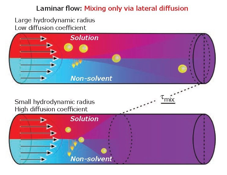
This leads to the problem. With no lateral convection in a laminar flow, mixing is only based on diffusion, with mixing times typically scaling as τmix ̴ d2/D (d is the width of the fluid stream; D is the diffusion coefficient, inversely related to size, Figure 1). In short, the mixing is slow, especially for polymers. For example, a 1 kDa poly(ethylene glycol) (PEG) (D ̴ 3 * 10-10m2/s) ( solution in water would cover 100 μm in 30 seconds. In order to achieve mixing at 1 mL/min, a capillary would need to be at least 15 cm long.
The slow mixing is often a problem because it may lead to less desired but more thermodynamically stable products; e.g. microparticles (lower interfacial energy) instead of nanoparticles as a result of a slower precipitation process.

Figure 1.Two fluids moving parallel in a laminar flow mix laterally only through diffusion, which is increasingly slow as the size of the object increases.
Solutions developed to accelerate mixing
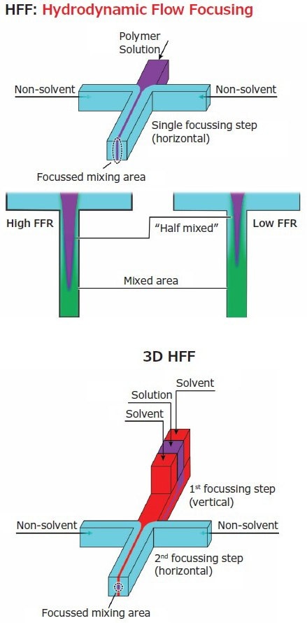
Often solvents and materials are selected to maximize reciprocal diffusion coefficients and often to minimize viscosity. More commonly, the geometrical features and/or the nature of the flow are engineered either acting on the area where the different fluids meet (the confluence point), or on the area immediately after (the mixing region of the chip). An example of the former approach is hydrodynamic flow focusing (HFF), which is based on the control over the width of a central flow that carries the material of interest and is squeezed by lateral flows (Figure 2, left).
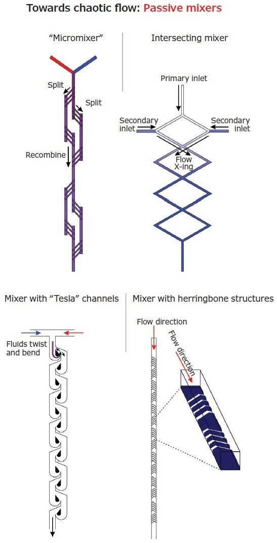
For the latter approach, the general aim is to transition from a laminar to a chaotic flow regimen. Although curvilinear channels can already provide some results, static or ‘passive’ (micro)mixers10 (Figure 3) typically have paths with complex shapes and obstacles. The chaotic character of the flow can be further increased with heterogeneities in the flow itself, e.g. with small amounts of high molecular weight polymers that alter viscosity at a microscopic level,9 or through the use of patterned surfaces.11 The mixing efficiency of static mixers is typically compared through the Peclet number ( is the length of the channel), which actually provides the ratio between mass transport through convection (chaotic flow), and that due to diffusion (laminar flow).
More complex approaches are based on ‘active’ mixers, where chaotic features are introduced via external fields through e.g. cavitation.12

Figure 2.In 2D HFF, two lateral flows squeeze a central polymer solution increasingly with their relative speed (flow rate ratio). The polymer solution spans through the height of the channel until fully mixed, but in the 3D version (right) further focusing confines it centrally.

Figure 3.Schematic structures of the most common passive mixers. The general aim is the creation of vortices, twists, or transversal flows in order to facilitate mixing orthogonal to the flow direction. Since these structures are introduced after the junction zone, these approaches are compatible with HFF.
Examples of microfluidic-assisted nanomanufacturing
Nanomanufacturing Via Phase Separation
The gold standard materials are hydrophobic polyesters such as poly(lactic-co-glycolic acid) (PLGA) or poly(caprolactone) (PCL), either combined with surfactants or blocks of macroamphiphiles (amphiphilic block copolymers) containing PEG as hydrophilic component (Table 2, top section). Of note, macroamphiphiles can yield smaller colloids than hydrophobe/surfactant combinations, because immediately after nucleation the particles already feature a hydrophilic surface that stabilize them; however, they may yield heterogeneous morphologies (micelles, polymersomes, worm-like or filomicelles)13 due to the small energy differences between these self-assembled structures.
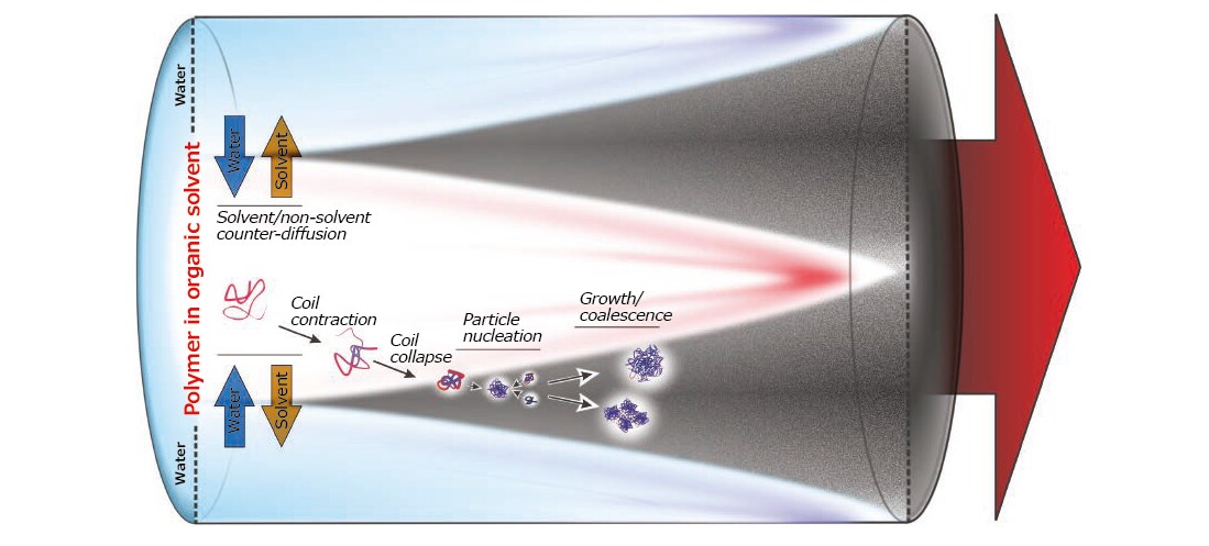
Phase separation folllows the mixing in a (polar) organic solution of a polymer with a non-solvent, most often water (Figure 4). The conditions of thermodynamic insolubility (the spinodal decomposition) depend primarily on non-solvent content and temperature, but the actual rate at which particles nucleate are mostly affected by polymer concentration, amount of non-solvent in excess to the critical composition and diffusion coefficients of solvent, non-solvent and polymer (all affected by the medium viscosity).

Figure 4.Different steps of phase separation (nanoprecipitation) in a flow-focused geometry. There are multiple levels of kinetic control: A) the mass transfer of solvent and non-solvent molecules through the phase boundary, leading to contraction and then collapse of macromolecular coils in the polymer-rich phase; B) the diffusion of collapsed polymer coils (globules) and their collisions eventually leading to particle nucleation; C) the increase in particle size due to anelastic collision and merging (coalescence) of particles (less likely with decreasing solvent content), or the incorporation of further individual macromolecules. The final average size of the particles and their average size distribution will therefore exhibit a complex dependence on the diffusion coefficients of the various species, on the overall flow rate and flow rate ratio, and on the polymer concentration.
In short, on the top of a thermodynamic basis, nucleation strongly depends on the mass transfer between the two phases during mixing. After nucleation, aggregation continues along two directions: 1) the addition of polymer chains onto growing particles, whose rate depends on concentration and diffusion coefficients of both, but also on the nature of the nanoparticle surface; 2) the coalescence of growing particles, which is facilitated by incomplete migration of the organic solvent into water and plasticizes the polymer; the coalescence rate again depends on the mass transfer of the solvent, and on the particle concentration and diffusivity. Importantly, this description applies to (nano)precipitation and to a certain extent to emulsion/vesicle formation, but point 2 does not generally apply to equilibrium processes, such as micellar self-assembly.
The most common parameters used to control mixing and thereby particle dimension are a) the total flow rate (TFR), and b) the flow rate ratio (FRR), i.e. the ratio between the velocities of the polymer solution and water, which also indicates the overall organic solvent/water composition. Reportedly, FRR has a higher influence on the final particle size; the lower the FRR (see also Figure 2, left), the more rapidly the critical nucleation concentration is attained, which leads to an accelerated particle formation (although the nucleation rate is not necessarily affected) with a resulting reduction in average size5,6,14,18 and width of the size distribution. Further, the faster kinetics reduce the chance of extra-particle crystallization of drugs, allowing for higher encapsulation efficiencies.14,18 TFR apppears to have a less noticeable effect on particle size; yet, when mixing is favored by a higher overall flow (e.g. in HFF) or by a (semi) chaotic flow,7,14,15 higher TFR leads to a lower particle size. TFR reportedly may also affect polymer crystallinity and above all the morphology of self-assembled block copolymers (from spheres at low TFR, to filomicelles and lamellae at higher TFR).13 The influence of TFR on drug encapsulation is less clear, with reports of opposite effects depending on the microfluidics system, drug and polymer used.13-15
Two other control factors are the polymer molecular weight (MW) and the viscosity of its solution; the latter in turn depends on molecular weight itself, concentration, and architecture of the polymer. A higher MW of hydrophobes (whole polymers or blocks in amphiphiles) is often suggested to increase particle size,17,18 although sometimes no influence is reported.6 The main underlying phenomenon is likely the lower solubility with increasing macromolecular size (= coil collapse happening faster during solvent exchange), but mixing conditions may complicate its influence: with a very rapid mixing, a higher MW may also increase the nucleation rate, possibly leading to more numerous but smaller particles. The effect of hydrophobicity may be similar in nature: more hydrophobic chitosans produce smaller particles18 possibly because of higher nucleation rate.
For what attains to viscosity, an increase in particle size may be seen, but only when viscosity is significantly increased,14 which may also be beneficial for the encapsulation efficiency;16 however, high viscosity may be detrimental for mixing above all at the channel walls, leading to macroscopic aggregation and/or deposits.
Nanomanufacturing via cross-linking
The formation of a physically or chemically bound network can be used to generate nanoparticles if two interacting partners, typically dissolved in the same solvent, are appropriately mixed (Table 2, bottom section). Typically, neither coil transitions (e.g. collapse), nor particle coalescence occur significantly, and the main process determinants are the mass transfer between the two phases, the nucleation rate and the mechanism of particle growth. The most common approach utilizes polyelectrolyte complexation (polyanions such as alginate or nucleic acids, + polycations such as poly(ethylene imine) (PEI), poly(L-lysine) (PLL), chitosan or even calcium) as a cross-linking event. This is more popular than chemical cross-linking due to a better control over particle growth: using one reagent in excess, it is possible to obtain charged (self-repellant) particles grown mostly by addition of individual chains rather than through agglomeration. The nucleation rate typically depends on both the cation/anion concentration and their balance (also affected by pH), the ionic strength and the size of the two partners.
A major issue is the homogeneity and compactness of the nanoparticle bulk, which is often expressed through its mesh size. In this regard, the substantial irreversibility of the polyelectrolyte complexation makes the processes essentially kinetically controlled. For example, networks obtained by crosslinking alginate with a more avid and less diffusive polymeric cation are less homogeneous than those cross-linked by calcium ions; however, a higher nucleation rate (e.g. through disruption of laminar flow)23 may yield more compact nanoparticles. Generally microfluidics provide more controlled mesh size and better bulk compaction22 than batch processes, as evidenced by the higher surface charge (hence higher stability)24 and lower cytotoxicity (less free polymer in solution).20
Importantly, in these approaches electrostatic interactions are most often used also to load bioactive components , which allows for encapsulation efficiencies much higher than in phase separation-based processes, which utilize partition and/or entrapment (typically efficiencies ranging 70-100% in one case vs. up to 20-30% in the other). As a result of a more firm loading, the release from polyelectrolyte complexes is seldom diffusional, and therefore typically features hardly any burst and a long duration.22,23 More commonly, degradative events or a weakening of the electrostatic complexation are required to obtain significant drug delivery.
Conclusions and outlook
Microfluidics can assist nanomanufacturing through different mechanisms, most popularly through phase segregation (nanoprecipitation, self-assembly), but also polyelectrolyte complexation. The advantages over more conventional batch processes are in the reproducibility, tunability and at least partial scalability of the processes, which lends well to the development of personalized medicines.
Currently, the main areas for development are in a) the fluidodynamics of chaotic mixing, which promise a better control over size and loading, but where a detailed mechanistic understanding of aggregation is still lacking; b) the industrial scalability, since larger channels may lead to different flow regimes, and parallelization is often costly.
References
若要繼續閱讀,請登入或建立帳戶。
還沒有帳戶?